真空管試験機、真空管試験器 (Tube Tester、Valve tester) のお話し
真空管の製造メーカは、色々な種類の真空管の規格(特性)を決めて製造しています。
真空管の規格は、汎用品種(ラジオ、テレビ、増幅器(アンプ)などに利用される球)については、各国(日本、米国、英国など)毎に統一された品種名と対応する規格が定められていました。戦前の日本は、ほぼ米国に倣った(同様の)品種名と規格で真空管を製造しています。
真空管試験機はどのような場面で必要となるのか。
真空管の製造メーカは、規格に適合する真空管を出荷(市販)していますので、いわゆる初期不良も極めて稀です。真空管は保存しているだけならば、その規格(特性)が変化(劣化も、向上も)することは先ずありません。
しかし、規格というものには、ある程度の巾があります。
高級なアンプ類、エンコーダ、デコーダや高精度の通信機器、計測器に利用する真空管では、その球の特性をそろえることが重要な場合があります。
また、真空管は他の電気製品と同様に使用時間に比例して、その規格(特性)が変化します。この変化は、かなりゆっくりですが、規格以上の負荷を加えた場合などは急速に劣化する、あるいは破損する場合もあります。
そこで、真空管試験機の出番です。
ところで、真空管試験機は各種の真空管の特性を試験することを目的とした計測器です。
真空管の特性を「測定する」とは言わずに「試験する」と言うのは、一般的な(市販されている)真空管試験機は、メーカの設備ではありませんので、真空管の規格、特性の全てを測定することは出来ません。
そこで、通常は、真空管試験機、Tube Testerと呼んでいます。
真空管試験機の種類
1.
フィラメント(ヒーター)チェッカー
真空管の劣化で一番多いのは、電球と同じようにフィラメントが切れる(断線する)現象ですので、これをチェックするためのものです。
ラジオ、テレビの保守要員が利用していました。
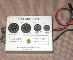
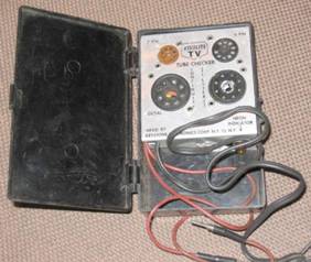
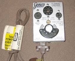
フィラメント(ヒーター)チェッカーの例
2.
エミッション計測型の真空管試験機
エミッションとは、真空管の陰極(ヒーターあるいはカソード)から放射される空間電流のことです。不思議なことに訳語がありません。
真空管が使えるかどうか(良品か不良品か)の判定の第一はフィラメント(ヒーター)が断線していないことです。
判定の第二は、エミッションが充分にあるかどうかです。
エミッション計測型の真空管試験機はこの機能を持つ真空管試験機です。
もちろん、フィラメント(ヒーター)が切れていればエミッションは0です。
真空管の良否判定の第一段階に有用です。
このタイプの真空管試験機は多くの計測器が製造していました。
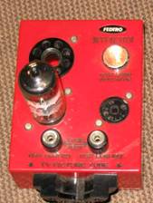
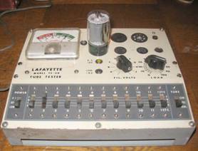
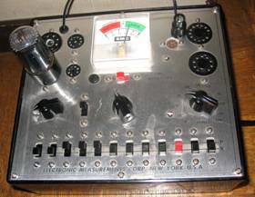
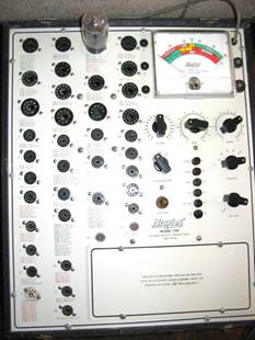
エミッション計測型の真空管試験機の例
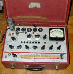
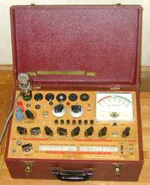
3.
相互コンダクタンス(gm)計測型の真空管試験機
真空管の3定数の一つであって極めて重要な相互コンダクタンス(gm)の計測機能のある真空管試験機です。
このタイプが最も多くポピュラーです。
特性の揃った球の選別には、このタイプの真空管試験機が必要です。
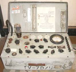
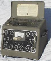
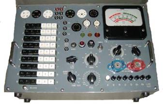
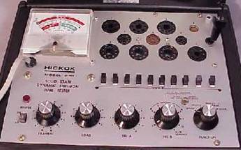
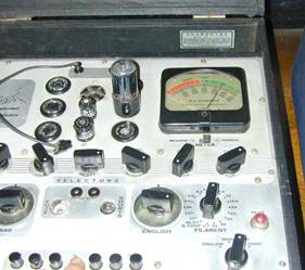
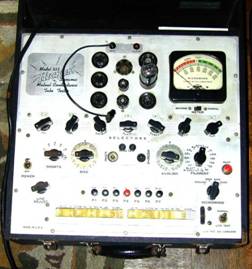
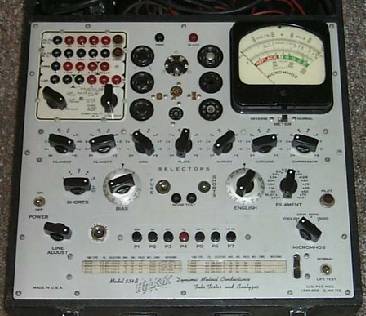
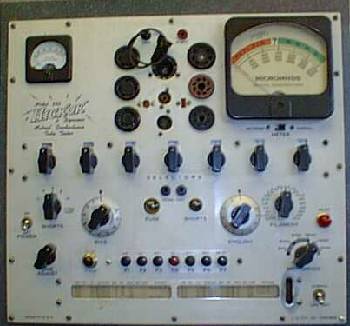
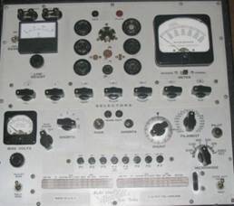
最も多く製造されて、今でも最も多く活用されているモデルは、米軍規格の機種の、TV7シリーズです。
第二次大戦中に前線での利用を前提に設計・製造されたもので、頑丈な造りです。
このシリーズには、(子番なし)、(A)、(B)、(C)、(D)の5モデルがあり、少しずつ機能が増えていますが、基本的な設計は同じです。
(C)モデルはカナダ軍用です。
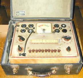
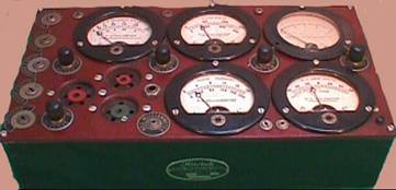
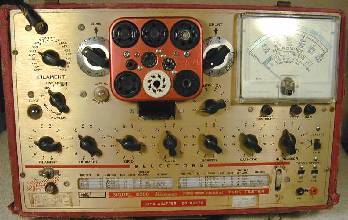
TV7シリーズの例
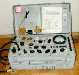
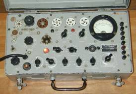
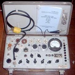
TV-7シリーズは第二次大戦中に大量に製造されました。
従ってその製造メーカも多くありますが、最も著名なメーカは、Hickok ヒーコック です。
このメーカはその他の計測器も製造していましたが、1920年代後半から戦後まで非常に多くの種類の真空管試験機を世に出していました。
今でも、Hickok のファンは世界中に大勢います。そして多くの機種は現役で活躍中です。
その他の真空管試験機の製造業者も次のように沢山ありました。
Acurate
AVO
B&K
Corner
Eico
EMC
Heath
Hickoc
Jackson
Knight
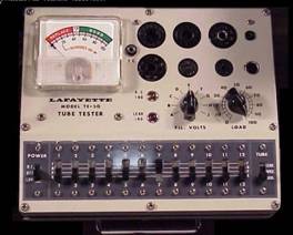
Lafyet
Lamp
Mercury
Neuberger
NRI
Precise
Precisio
Precision
Seco
Sencore
Simpson
Stark
Superior
Sylvania
Tayler
Teck
Tektonics
Triprett
等々です。
ご興味のある方は、検索サイトで、「tubetester+メーカ名」で検索して見てください。
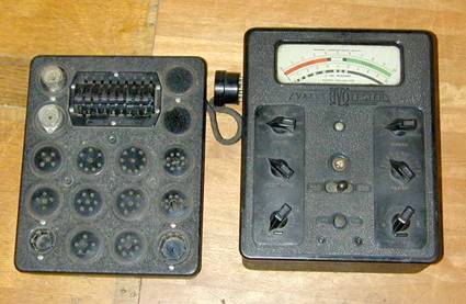
上記の中で、AVOとTayler は英国のメーカです。AVOは高級な真空管試験機の製造業者として、Hickok に匹敵します。設計内容の非常に高度で高い評価を得ています。もちろん現役で活躍しています。
AVO MKII
AVO 2パネル
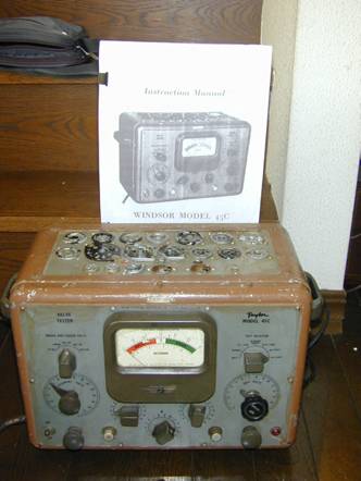
Tayler
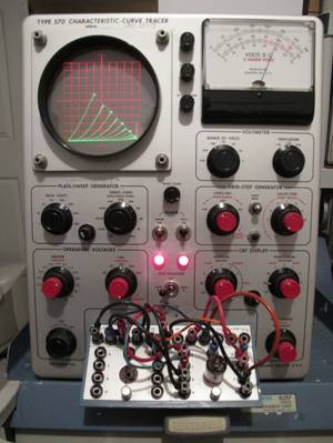
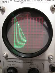
Tektonics はオシロスコープのトップメーカでしたが、ブラウン管上に真空管の3定数の曲線を表示する真空管試験機を製造していました。現在では極めて入手困難の機種です。
Lafyet は、日本のトリオ・・Kenwood・・からのOEM製品を販売していました。
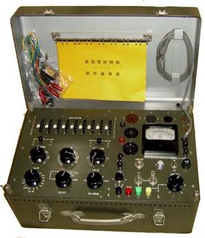
日本でも真空管試験機は製造されました。
トップメーカは、三田無線・・デリカ・・で最近までオーダー生産していたようで人気があります。
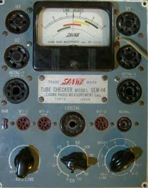
その他、国洋電気、三和計測器などでも主に自衛隊用の機種を製造していました。
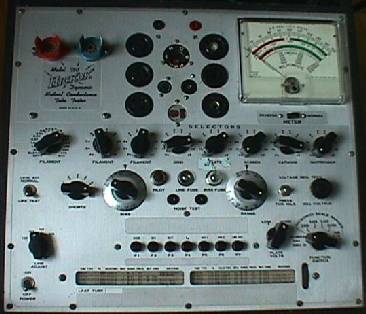
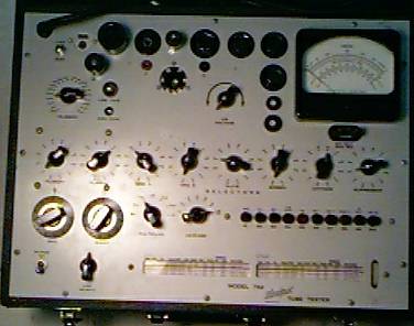
Hickok ヒーコック は計測器のメーカですが、1920年代から戦後のしばらくの間、多くの種類の真空管試験機を製造していた、最有力のメーカです。
あまりにも多機種に亘るので、全機種を紹介することは困難です。
次に幾つかを紹介しますが、大部分はμ測定タイプです。
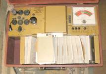
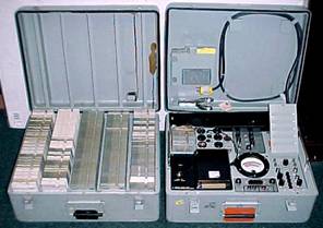
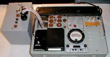
121,123、123A、123AM、USM-118A/Bの各機種はCardmaticと呼ばれる、カード挿入式で手動でのスイッチの設定が不要な機種です。
121は単純な計測方式ですが、その他のカードマッチックは披試験真空管の電極に供給する電圧を披試験真空管毎に変化させて、他の品種よりも精密な試験を行います。
この機能を活用して、パソコンで三定数を表示、印刷するアダプターが販売されていました。
AC-4600
121
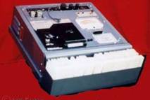
軍用123A
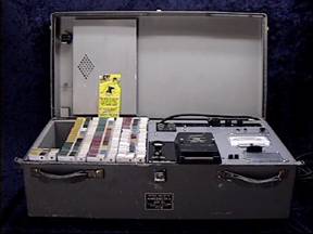
USM-118A/B USM-118A/B Computerized
230
534
539A
600
750
799
800

6000 6000A

Western Electric KS-5727 L1 Western Electric KS-15560 L1


Western Electric KS-15750 L1

真空管試験機の利用法
真空管を用いる機器の利用者は、その機器が故障した場合には、先ず用いられている真空管の良否を判定する必要があります。
そのために、真空管のメーカは各真空管の作動条件(規格)のマニュアルを発行していました。
この規格に適合するかの試験をすることを目的とする計測器が真空管試験機です。
この試験は、主に次の項目です。
1.
短絡試験
この試験は真空管内部の電極間のショートを検査します。
2.
エミッションテスト
カソード(陰極)からアノード(陽極・・・プレート)へ電流が正常に流れているかを検査します。
3.
相互コンダクタンス試験
この試験の目的は、真空管の増幅性能を計測するものです。
真空管試験機の試験方式
真空管試験機の試験の方式(原理)は、Hickokに代表される米国方式と、AVOに代表される英国方式が主な方式(原理)に分けることが出来ます。
1. 米国方式
真空管のプレートとグリッドに電源脈流を印加し、不平衡電流を読む方式です。
精度はそれほど高いものではありませんが、真空管の良否判定には充分な精度を持っています。TV-7シリーズも同じ計測原理のものです。この機種はGMの値を直読出来ませんが、その他の Hickokの機種は殆どは、GM直読形式です。

相互コンダクタンス試験の原理を簡単な説明。
上の図のトランスの二次巻線から全波整流管のプレートに電圧が加えられます。二次巻線の内側の間には直流電流計が接続されています。
この. A
center-tapped resistor,
RM, is shunted across the milliammeter. The load, resistance RL, is connected
between
the center tap of the transformer (momentarily neglecting resistor RM) and the
cathode
of the rectifier, as in common full-wave rectifier circuits. When plate 2 is
positive with respect
to the cathode, electrons flow through the upper half of resistor RM and through
RL, to
the cathode, causing the meter pointer to deflect in one direction. When plate 1
is positive
with respect to the cathode, electrons flow through the lower half of resistor
RM a n d
through RL to the cathode, causing the meter pointer to deflect in the opposite
directior With
the load resistance fixed and with equal forces acting upon the meter each time
the tube conducts,
the meter pointer will indicate zero. The pointer cannot follow to oprent
variations
Figure 4. Rectifier diagram.
at the rate of conduction of the tube because of the inertia of the meter
movement.
b. If the amplifier tube to be tested is substituted for the fixed load
resistance and a
fixed bias voltage E is applied to the tube (fig.5), the meter will still
indicate zero because
the amplifier tube, under steady-state conditions, acts like a fixed resistance.
c. If, in addition to the bias voltage, an ac potential is applied between the
control grid
and the cathode of the tube under test, the circuit becomes equivalent to the
one used for
mutual conductance tests in the TV-7(*)/U. When the ac potential causes the bias
voltage
between the control grid and the cathode to become less negative, plate current
through the
tube will increase. Since the plate-cathode resistance has decreased, more
current will flow
through resistor RM , and the deflecting force on the pointer of the meter will
be greater than
before the ac potential was applied. When the ac potential causes the bias
voltage between the
control grid and the cathode to become more negative on the other half cycle,
the resistance
of the tube under test will increase, plate current will decrease, and the
deflecting force on
the meter pointer will be less. With unbalanced current flow through the meter
on adjacent half
cycles and consequent unequal forces applied to the pointer of the meter, the
deflection of the
pointer will be proportional to the difference between the currents. Since the
difference between
the currents was created by the ac potential applied between the control grid
and the
cathode, the meter pointer will indicate the plate current changes produced by
the applied
grid voltage change. The meter, therefore, will indicate the mutual conductance
(para 10a) of
the tube under test.
The
Cardmatic tube tester is an ingenious design. Various power supplies, a gm
bridge circuit for measuring transconductance, a decade resistor box, and an
accurate metering circuit are all connected together at the card reader so that
anything can be connected to anything. Replace the card reader contacts with
relays and you have an ideal platform for computer control.
The tester is capable of at least 17 different test configurations, ranging from
simple triode transconductance tests to high voltage rectifier tests to voltage
regulator tests.
We'll start with the shorts test. One of the functions of the power supply is to
supply a regulated positive and negative 150VDC. Among other things, these
voltages are used for the shorts tests. They are applied to the tube elements in
the opposite polarity from normal. This means no worry of cathode stripping, and
any sort of grid emission will cause a short lamp to flicker. If there is enough
leakage between any elements to allow enough current to flow to light a neon
lamp, then the tube is defective. The sensitivity of the shorts test is
adjustable and is part of the calibration procedure.
At the same time, the meter is placed in series with the heater and cathode to
measure heater/cathode leakage. The meter can be programmed to reject tubes with
as little as 10 uA of leakage current or as much as 170 uA. It can also be
disabled, which is done in the case of directly heated filamentary tubes.
For the quality test, the tester can be configured a number of ways depending on
the tube to be tested. Here are some examples:
Transconductance Test:
Full scale meter reading can be programmed from 500 to 128,000 uMhos in 100 uMho
steps.
The tube can be in grid bias or self bias mode.
Negative grid bias, if used, can be set to -.1VDC to -99.9VDC in .1 volt steps.
In self bias mode, the cathode bias resistor can be anywhere from 0 ohms to 70K
ohms in 10 ohm steps.
In self bias mode, the cathode bias resistor can be bypassed by a 1000uf
capacitor.
A regulated signal voltage of .222VAC is applied to the grid.
The plate voltage is regulated and can be from 10VDC to 260VDC in 10 volt steps.
Plate Current Test:
Full scale meter reading can be programmed from 100 uA to 500 mA in 100uA steps.
The tube can be in grid bias or self bias mode, or can be a diode.
Negative grid bias, if used, can be set to -.1VDC to -99.9VDC in .1 volt steps.
The plate circuit resistance can be set anywhere from 0 ohms to 70K ohms in 10
ohm steps.
The plate voltage is regulated and can be set from 10VDC to 260VDC in 10 volt
steps, or an unregulated 360VDC, or up to 1200V P-P AC.
"Knee" Test for Sweep Tubes
High current test where the tube is having to charge/discharge a large
capacitance as its load. Most testers lack this test.
These are just a few of the more common tests, and we've already hit quite a few
different combinations of test configurations. Since most of the more obscure
test configurations are used only for tubes that are already programmed into the
database we will not go into details here.
During the gas test, the tester simply measures grid current. If there are gas
ions present in the tube, they will be attracted to the negative grid and grid
current will flow, causing the meter to deflect. If it deflects above the green
area for gas, then more than 3 uA of grid current is flowing and the tube should
be rejected.
This tester also has:
A filament power supply that is programmable from .1 volts to 119.9 volts in .1
volt increments.
An auxiliary B+ supply that is regulated and continually adjustable from 30 to
300 volts (used mostly for voltage regulator tube tests).
A bias off supply that is used to keep unused tube sections biased off during
tests.
A test button that allows us to test two identical sections within a tube with
one test.
Protection circuits that automatically shut the tester off in case of power
supply overload or grossly off scale meter deflections.
All in all, one nice tester!
2. 英国方式
英国には多くの真空管試験のメーカがあるわけではありませんが、方式はAVOの製品意倣っています。

Measurement of mutual conductance (= transconductance) is based on a sophisticated operational principle using a transistorized high frequency (HF) oscillator and a frequency selective HF amplifier (fig. 2, High Pass Filter & Amplifier). The grid BIAS signal and the HF signal are added and routed to the grid of the test tube. Detailed schematics are shown in figs 7 & 8.
Figure 2: Basic circuit for mutual
conductance measurement
(Source: Operational Manual)
Below, a few voltage measurements performed to clarify the principle of mutual
conductance measurement as used in this premium instrument developed by AVO are
presented.
The amplitude of the negative 50 Hz grid BIAS voltage can be selected in four
ranges from 0-100 Volt. This BIAS voltage is superimposed by a low voltage grid
HF signal the amplitude of which is well stabilized. HF modulation of the grid
voltage results in a proportional plate HF current. Mutual conductance is
derived from the band-pass filtered plate HF current set into relation to the
applied grid HF signal amplitude.
The following voltage measurements were registered using a Tektronix TDS 210
oscilloscope. There was no test tube inserted into the VCM 163.
Due to the fact that the high frequency grid signal is magnitudes smaller than
the UgridBIAS amplitude the superimposed grid signal is not readily
visible (figure 3).
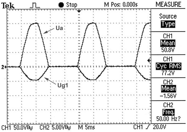
Figure 3: Simultaneous display of Uplate and
Ugrid (50 Hz frequency)
Channel 1: positive half wave plate voltage (Uplate) at 50V/div
Channel 2: negative half wave grid voltage (Ugrid) at 5V/div
To visualize the grid HF signal ‘riding’ on the 50 Hz grid BIAS supply
amplification was increased from 5 Volt to 0.2 Volt per division.

Figure 4: Ugrid at
higher amplification (200mV/div)
Especially in the horizontal parts of Ugrid recording
the superimposed HF grid signal now becomes noticeable as wide traces (fig. 4,
arrow). For further clarification of the combined signal to the grid figure 5
illustrates the grid HF signal component using higher amplification (20mV/div)
and faster time deflection (50µs/div).
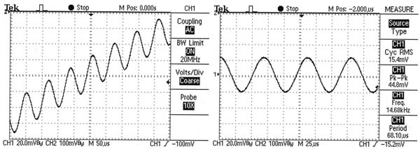
Figure 5: Grid signal (Range 0-6 mA/V)
Left insert: Grid HF signal at the rising part of the 50Hz BIAS sine wave
Right insert: Grid HF signal at zero BIAS voltage
Frequency of the grid HF signal (not mentioned in any AVO manual) was found to
be 14.68 kHz.
The AVO VCM 163 offers three selectable ranges
for mutual conductance measurement by switching the amplitude of the grid HF
signal.

Figure 6: Grid HF signals at 3 selectable mutual conductance ranges
Voltages shown in the MEASURE panel (right-hand side) correspond
to the 0-6 mA/V range
Tubes with low mutual conductance (0-6 mA/V) are measured using a large
amplitude grid HF signal whereas tubes with high (0-20 mA/V) or very high mutual
conductance (0-60 mA/V) require lower signal amplitudes.
As a general purpose tube tester the VCM 163 in addition to the above described
features is able to:
• check the heater continuity
• measure insulation between electrodes with the tube either being cold or
hot
• check rectifiers and diodes under load conditions
• measure gas current up to 100 µA f.s.d.
A remarkable highlight of the mechanical sturdy construction of the instrument
is the use of a huge thumbwheel switch 13 pin electrode selector (cf. fig. 1).